Product - Road Simulators
Road Simulators
Applications for Road Simulators
- Durability
- End-of-Line Production
- Noise, Vibration and Harshness (NVH)
- Research & Development
- Buzz, Squeak and Rattle (BSR)
- Accelerated Life
Benefits of Servo Electric Actuator Road Simulators
The key benefits of SEA-based road simulation testing technology include:
Improved Reliability: A less complicated actuator assembly resulting in fewer parts yields an increase in reliability and lower maintenance costs.
Higher Accuracy: SEA systems are not affected by many physical constraints that cause reduced system accuracy and repeatability. These variables include oil viscosity changes with temperature, accumulator pressure, servo valve wear, flow restrictions, seal friction, hydraulic resonances, and oil contamination.
Increased Performance: SEA can achieve higher velocities at higher forces, with 3X higher frequency response, resulting in lower RMS errors than hydraulic systems.
Greater Efficiency: In comparable use cases, SEA systems use less than 20% of the electrical energy compared to hydraulic systems.
Safer Operation: The SEA eliminates the potential for high pressure oil leaks and related environmental pollution. The SEA also utilizes safety integrated functions that allow for safety limited acceleration, velocity and force (current) to be configured for specific applications or testing.
Improved Troubleshooting: Smart diagnostics capability within the controls can direct operators to the specific hardware causing a fault condition. Remote log-in capability allows eMpulse engineers to aid in troubleshooting anywhere in the world.
Reduced Maintenance: Servoelectric actuators are compact, easy to install, and require minimal maintenance, resulting in lower overall system costs.
Cleaner Environment: Hydraulic fluids can be hazardous to the environment, and the process of disposing of used fluids can be costly and complex. Servoelectric systems do not require any fluids, making them a cleaner and safer alternative.
Spec Sheet
For more in depth information about the specifics of road simulators please download our the spec sheet.
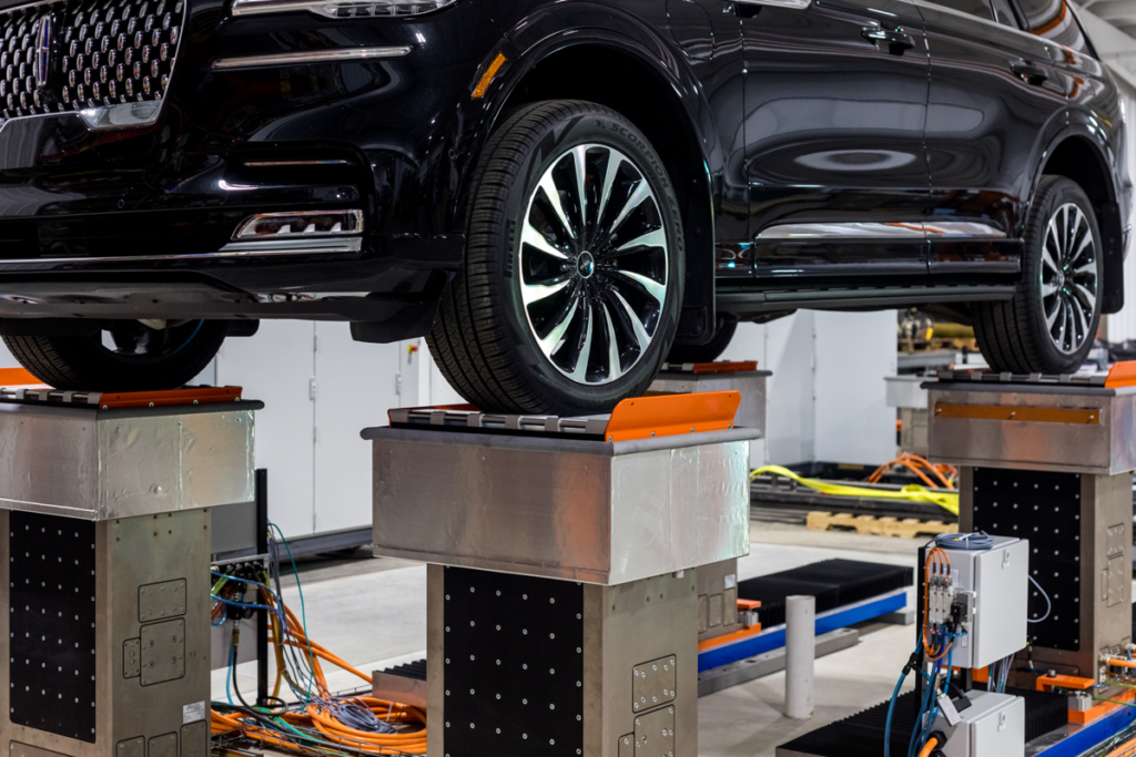
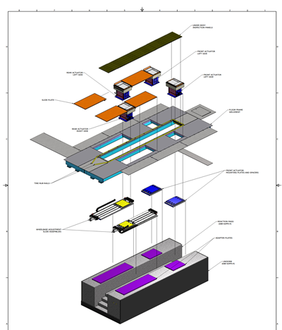
4 Poster Construction
Reaction Mass
Wheelbase Adjustment
Top Frame or Chamber Floor
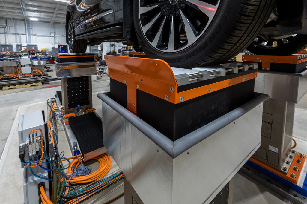
Actuators
Road Simulator Facility Integration Services
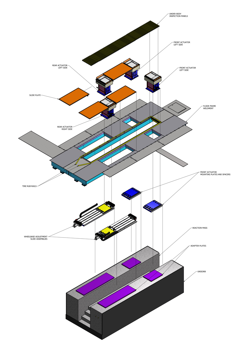
A reaction mass is required due to the phenomenon described by Sir Isaac Newton, in that every reaction has an equal and opposite reaction. When we are subjecting a vehicle to a test a force is applied to the vehicle through the wheels in the vertical direction, an equal force is therefore applied to the test rig in the downward direction.
The design of the reaction mass will depend upon the application of the 4-poster typically they will be 70 to 160 Ton depending upon the application. The channel in the top centre allows engineers access to the underside of vehicles under test to carry out under body instructions. The Grout Plates shown in purple are then set in place and groted level taking up any unevenness in the top of the reaction mass which will occur when it is drying as it needs to be poured in one.
To allow for vehicles of different wheelbases it is necessary to have a system that can move at least one set of wheels.
eMpulse systems are automated with real-time feedback for the operator. The standard wheelbase adjustment system has an adjustment travel of 1.4m with the optional long-travel range of 2.4m.
When the Vehicle needs to remain in the centre of the Chamber eMpulse can also supply a system to move all 4 actuators which will allow the vehicle to remain in the center position of the chamber. The standard wheel pan size will still accommodate the stated track width requirements so no actuator position system is needed for track width adjustment.
Automated wheelbase adjustment allows the operators to see the current wheelbase length and adjust the location with the click of the mouse. Wheelbase change time is less than 3 minutes, typically adjusting the rear actuators only. An audible buzzer is activated when the wheelbase adjustment system is moving to warn nearby personnel of any potential hazard. A vehicle detect photo sensor and adjustable motor overloads are provided to protect against wheelbase adjustment when a vehicle is present on the 4-poster.
The top-frame’s proven design will allow for underbody inspection of the vehicle through an opening along the centerline of the vehicle. The typical top frame will have removable fiberglass grating to cover underbody inspection opening. If however the installation is in an environmental chamber, eMpulse will work with the Chamber supplier to ensure the complete integration of 4-Poster and Climatic Chamber.
A range of different actuators are available with different strokes and power to meet the need of NVH and Endurance testing of vehicles up to 6 Ton gross weight.
The actuator assembly is modular and can accept a number of different motor and permanent magnet combinations, to optimally match the continuous and peak force, as well as the required velocity, to the test requirements.
The DC Brushless Linear Servo Motors operate on a DC Bus Voltage, which is obtained from a 3-phase AC rectifier circuit referred to as a Line Module. The incoming power is 380-480Vac, and typical performance specifications are based on the lower end of this range. Thus, higher capacities are available when operated on higher voltages available common in most areas. No transformers are required.
The motors are designed with liquid cooling to the fixed forcer, or primary, which is significantly more effective at removing heat which limits the continuous force ratings of servo electric motors. In addition, liquid cooling provides much quicker recovery from peak loads, providing more uptime and higher duty cycle usage than other air-cooled designs. In addition, both power cables and liquid cooling are designed to be fixed, as only the secondary magnets are moved. This further eliminates the failure modes of cable flex and cooling line ruptures.
The actuator assembly includes an Absolute (not Incremental) high resolution optical encoder. Resolution internal to the motor controls is 1nm, with 1um resolution available for data analysis.
The Drive Cabinet houses all servo drive components, including the Main Disconnect, the 3 phase high voltage Active Interface Module (line conditioning/filter/isolator), the Active Line Module (AC/DC Rectifier), the Motors Control Unit, and the Motor Modules for controlling and driving the commutation commands to the servo motors. Additional components include the dual redundant KTY/PTC internal thermal sensors monitoring, the incoming 3-phase voltage sensing module, and the redundant safety relay. All components employ the failsafe Safe Torque Off (STO) safety features inherent in the drive components and are hardwired through the redundant safety contacts of the safety relay. NVH 21kN Four Poster systems use a dual Rittal TS8 double bay cabinet, while the higher capacity 41kN systems use two sets of these dual TS8 double bay cabinets.
eMpulse has selected Siemens as their preferred partner in the development of this series of linear motors and controls. All components communicate to the control unit via a Drive-Cliq interface. In addition, communications from the servo components to the Tiab servo controller is via a high speed isochronous real-time Ethernet communications protocol called Profinet. All internal drive parameters and signals are thereby available to the Tiab servo control for monitoring, control, and diagnostics, without inducing electrical noise that is inherent in typical analog-to-digital and digital-to-analog interfaces used in competitor’s products.
The 4-Posters are controlled using a Tiab servo Electric controller to which eMpulse owns the IP for both hardware and software. .
The Tiab S2M servo controller is housed in a compact industrial 10U rack enclosure. The Tiab incorporates embedded Profinet communications hardware to communicate digitally with the servo drives. This enclosure also contains a rack mounted control PC and UPS (Uninterruptible Power supply). The control PC uses a standard Windows 7 or later operating system and provides an easy to use graphical user interface for system operation. This control PC communicates with the Tiab controller via a standard USB2.0 interface.
eMpulse can also supply the optional MIMIC (Multi-Input, Multi-output Iterative Control) Software can be provided to accommodate all drive file development.